
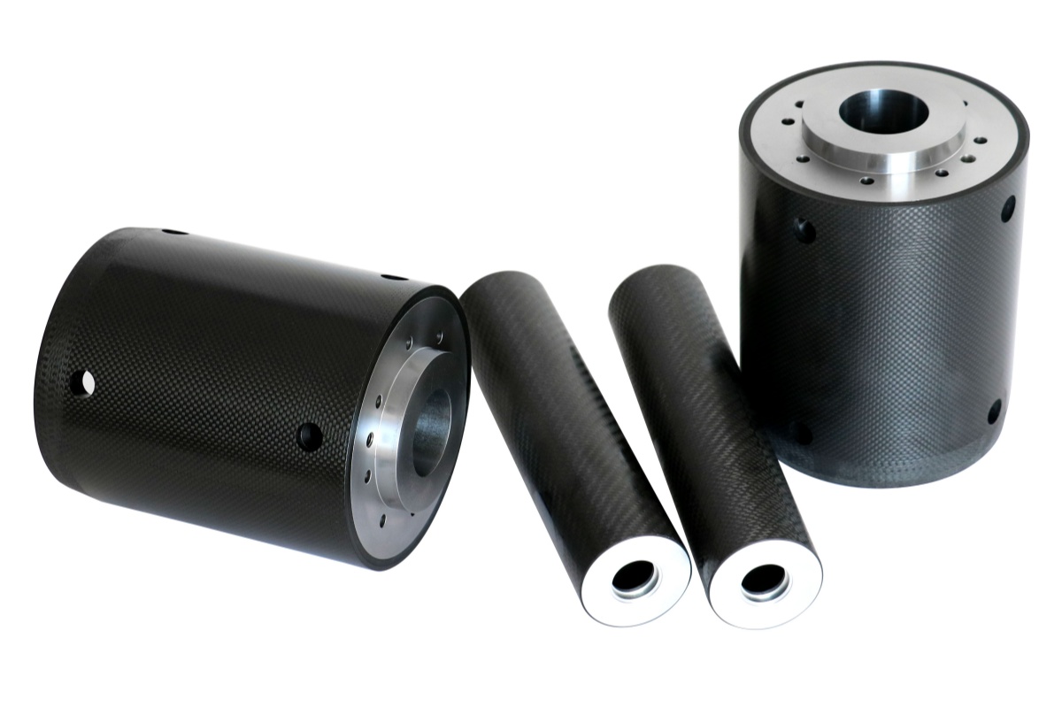
Xinbo Composites customs and manufactures carbon fiber idler rollers in roll-wrapped or filament winding construction, with ISO 9001-certified production and machining capabilities for precision bore and end-fitting integration. We custom carbon fiber rollers to fit your projects, based on drawings of OD, length, shaft type, operating RPM, web tension, radial load, temperature range, required TIR, balance grade, and end-fitting material.
Carbon fiber idler roller are used in high-speed web handling, printing, laminating, and converting lines where low mass, high stiffness-to-weight performance, controlled runout, and dynamic balance are critical. Compared with steel or aluminium rollers, a properly designed carbon fiber roller can reduce mass, lower bearing loads, reduce drive inertia, and improve deflection control over long spans. Actual performance depends on fibre grade, layup, OD, wall thickness, end-fitting design, and balancing requirements.
- Deflection: Depending on OD, wall thickness, layup, and fibre modulus, a carbon fiber roller can significantly reduce mid-span deflection compared with an aluminium roller of the same OD and span under equivalent radial load. In validated designs, reductions of 50-65% may be achievable.
- Weight: Carbon fiber rollers are typically 60-80% lighter than steel rollers of comparable geometry, reducing bearing loads and drive inertia.
- Critical specification points: Required axial flexural modulus, layup schedule or performance target, TIR tolerance, void content, end-fitting design, adhesive selection, and galvanic isolation.
Why Specific Stiffness Is the Primary Specification Parameter
The structural performance of a carbon fiber idler roller is driven by stiffness-to-weight ratio, not weight reduction alone. A roller under radial load behaves like a simply supported beam: mid-span deflection affects web tension variation, tracking error, and print registration accuracy. Because stiffness is layup-dependent, the required mechanical performance should be specified explicitly instead of being inferred from fibre grade alone.
- Specify axial flexural modulus: State a minimum axial flexural modulus on the drawing or in the technical specification, such as >=120 GPa when appropriate for the load case.
- 0°-dominant layup: A 0°-dominant layup provides high axial stiffness-to-weight performance and is preferred when mid-span deflection is the main design constraint, especially for long-span rollers with L/D above 10:1.
- Wall thickness and OD: Sizecarbon fiber tube so mid-span deflection under full radial load does not exceed the process tolerance. Coating and laminating lines may require values around <=0.1 mm/m, while precision printing applications may require tighter limits.
- Rotational inertia: Lower roller mass reduces moment of inertia, enabling faster acceleration and deceleration while reducing stress on drive components, bearings, and nip mechanisms.
For web lines above 200 m/min or carbon fiber rollers with L/D above 10:1, confirm the deflection requirement with a beam calculation before finalising tube OD and wall thickness. Do not rely only on a supplier’s standard product offering.
Layup Direction and Wall Construction
Roller performance is layup-dependent. Fibre orientation in the tube wall determines axial stiffness, hoop strength, and torsional stiffness, and these properties are trade-offs.
- 0° UD dominant: Maximises bending stiffness for long-span idler rollers. This is the preferred construction when mid-span deflection is the design constraint.
- ±45° balanced layup: Increases torsional stiffness and is required when the roller transmits torque along the shaft axis, such as in driven roller applications.
- Hybrid [0°/±45°/90°]: Balances axial stiffness, hoop strength, and torsional load capacity. This is commonly used for general-purpose industrial roller assemblies.
- Void content: Specify void content below 2% per ASTM D2734 for precision roller tubes. Higher void content can increase the risk of out-of-round after OD machining and can create crack initiation sites under cyclic loading.
Specify either the layup schedule or the required mechanical performance, such as axial flexural modulus, torsional stiffness, hoop strength, and allowable deflection under load. Two tubes with identical OD, wall, and nominal fibre grade can differ significantly in bending stiffness depending on ply orientation.
Surface Finish and Runout Tolerance
Dimensional precision is the critical handoff between carbon fiber tube manufacturer and roller integrator. Geometric runout and straightness errors at the tube stage cannot be corrected by dynamic balancing or end-fitting machining.
- TIR (Total Indicated Runout): 0.025-0.05 mm on the finished roller OD may be required for precision web handling and printing applications, depending on roller length, OD, operating speed, and web tolerance.
- Straightness: A target below 0.1 mm/m total deviation over roller length is commonly specified for coating and laminating lines, with tighter values used for higher-precision processes.
- End face preparation: Remove peel ply or lightly abrade the bonding surface to Ra 1.6-3.2 µm before adhesive bonding of journal fittings.
- CNC machining: Use PCDtooling and controlled feed rates to reduce the risk of delamination at tube ends. Machining allowance and tolerance should be confirmed before final tube design.
End Fitting Design and Shaft Integration
End fittings are one of the most common failure points in carbon fiber roller assemblies. The CTE differential between carbon fiber, which is approximately 0 or slightly negative ppm/K in the fibre direction, and aluminium at approximately 23 ppm/K can generate thermally induced shear stress at the bond line. Galvanic corrosion can also occur at unprotected carbon fiber-to-aluminium interfaces in humid or wet environments.
- Adhesive: Use toughened structural epoxy or film adhesive with elongation to failure above 5% when thermal cycling is expected.
- Bond overlap: As a preliminary design rule, bond overlap is often specified at 2-3 times shaft diameter. The final value should be verified against torque, radial load, thermal cycling, adhesive properties, and safety factor.
- Galvanic isolation: Use a GFRP sleeve, insulating coating, or equivalent barrier between the carbon fiber tube bore and aluminium shaft. Aluminium journals in direct contact with carbon fiber can corrode rapidly in humid or wet industrial environments if no isolation or sealing is applied.
- Steel end fittings: Stainless steel 316 generally presents lower galvanic corrosion risk than aluminium when properly isolated and sealed. Direct carbon fiber-to-metal contact should still be avoided in humid environments.
Large diameter carbon fiber tubes for roller cores are available in roll-wrapped and filament-winding construction. Xinbo Composites can machine bore tolerances to H7 for direct shaft fitting when the roller design, tube geometry, and end-fitting requirements are confirmed in advance.
Dynamic Balancing Requirements
Residual imbalance in a roller generates a rotating centrifugal force that increases with the square of rotational speed. At operating speeds above 1,000 RPM, residual imbalance can generate significant dynamic loads and shorten bearing life if not controlled.
- Balance grade: ISO 21940 G2.5 is commonly used for printing and converting rollers. G1.0 may be specified for precision rollers, high-RPM operation, or processes with very tight registration requirements.
- Two-plane (dynamic) balancing: Required for rollers with L/D above 2:1. Single-plane balancing is generally insufficient for long-span idler rollers.
- Residual imbalance spec: State residual imbalance as gram-millimetre per plane (g·mm) at the correction radius, not balance grade alone. Balance grade does not define permissible force at operating speed without RPM and geometry.
- Re-balancing after machining: Any post-fabrication OD grinding, journal turning, or face trimming can introduce asymmetric material removal and requires re-balancing before installation.
| Application | Recommended Layup | TIR Tolerance | Balance Grade | Primary Risk to Specify Against |
| High-speed web handling (>200 m/min) | 0°-dominant UD | ≤0.025 mm | G2.5 / G1.0 depending on RPM and process tolerance | Mid-span deflection at L/D >10:1; residual imbalance at high RPM |
| Printing / converting | Hybrid [0°/±45°/90°] | 0.025–0.05 mm | G2.5 | Print registration error |
| Laminating / coating | 0°-dominant UD | ≤0.05 mm | G2.5 | Straightness deviation over roller length |
| Driven rollers (torque transmission) | ±45° dominant | 0.05 mm | G2.5 | Torsional fatigue and bond-line stress |
Xinbo Composites is an expert in customizing professional and precise carbon fiber idler rollers for various industrial applications. Please contact us if you want to develop carbon fiber rollers to replace metal rollers.